Loading cart contents...


Study of 4 Bit Adder And Subtractor Circuits
This training board is designed by Electromotive to Study 4 BitAdder & Subtrater Circuits. User can perform experiment of 2 input Half adder, 2 input Half subtracter, 3 Input Full Adder, 3 Input Full Subtracter and 4 bit Full Adder and Subtracter. With the help of working manual user can make the connections of the respective circuit and verify the truth table. The inputs and outputs of the ciruits are brought out on glass epoxy PCB with there connections connected to 4 mm metal sockets soldered on the PCB itself. The enclosure is duo combo of metal and plastic parts, this provides good finish and 3 core mains cord provided fool proof earthing to the equipment.
| Specifications | ||
|---|---|---|
| Power Supply | 0-5V @ 500mA | |
| Line Regulation | 0.1% | |
| Load Regulation | 0.1% | |
| Logic Input switches | 9 in Number | |
| Logic Output Indicators | 5 in Number | |
| Load Regulation CV | 0.1% | |
| Provided with required number of patch cords and well explained working Manual | ||
Gross Weight: 2.640 Kg
Dimensions (packed): 350 mm X 262 mm X 100 mm (LXBXH)
₹6,266
10 in stock
Related products
-
₹5,400
![]()
![]()
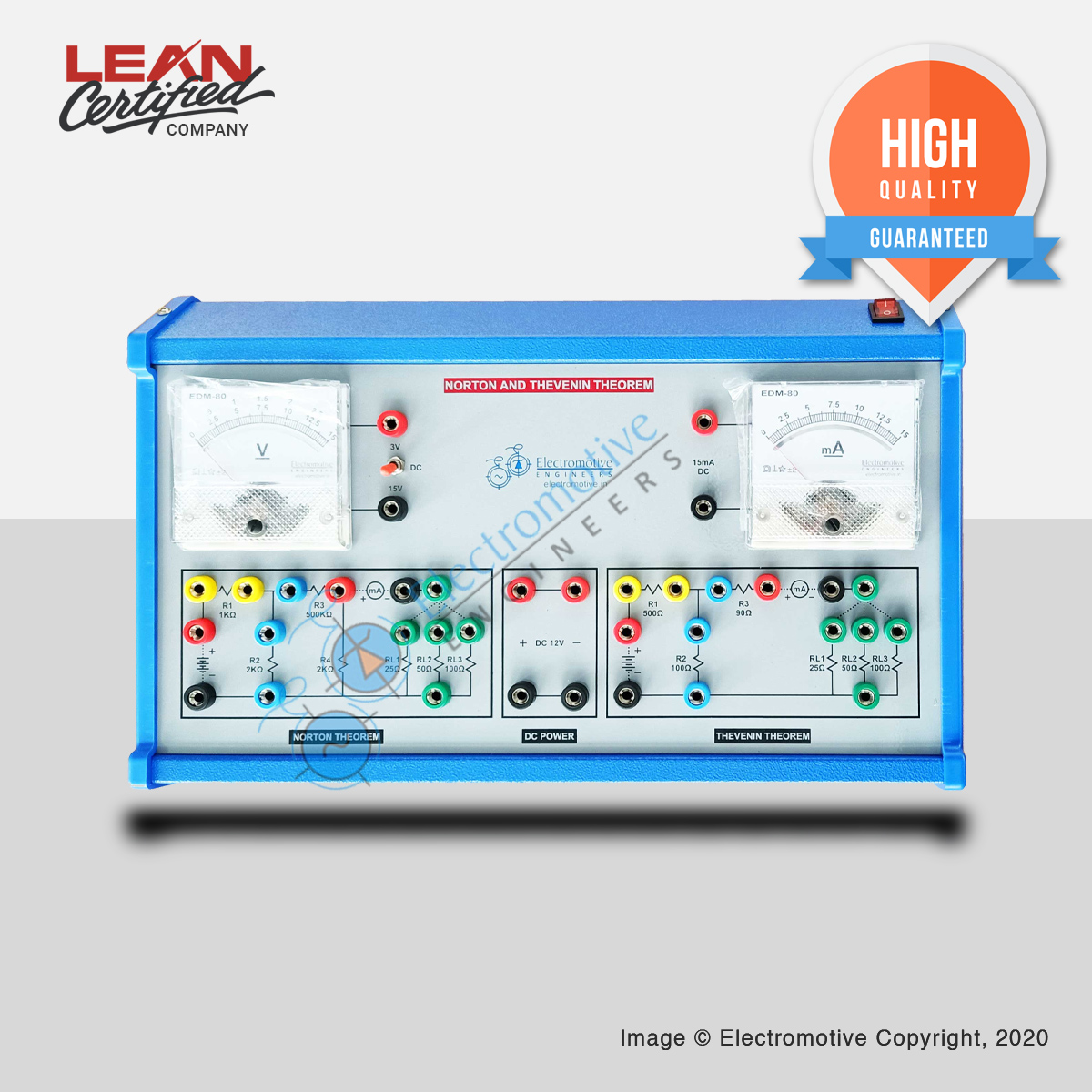
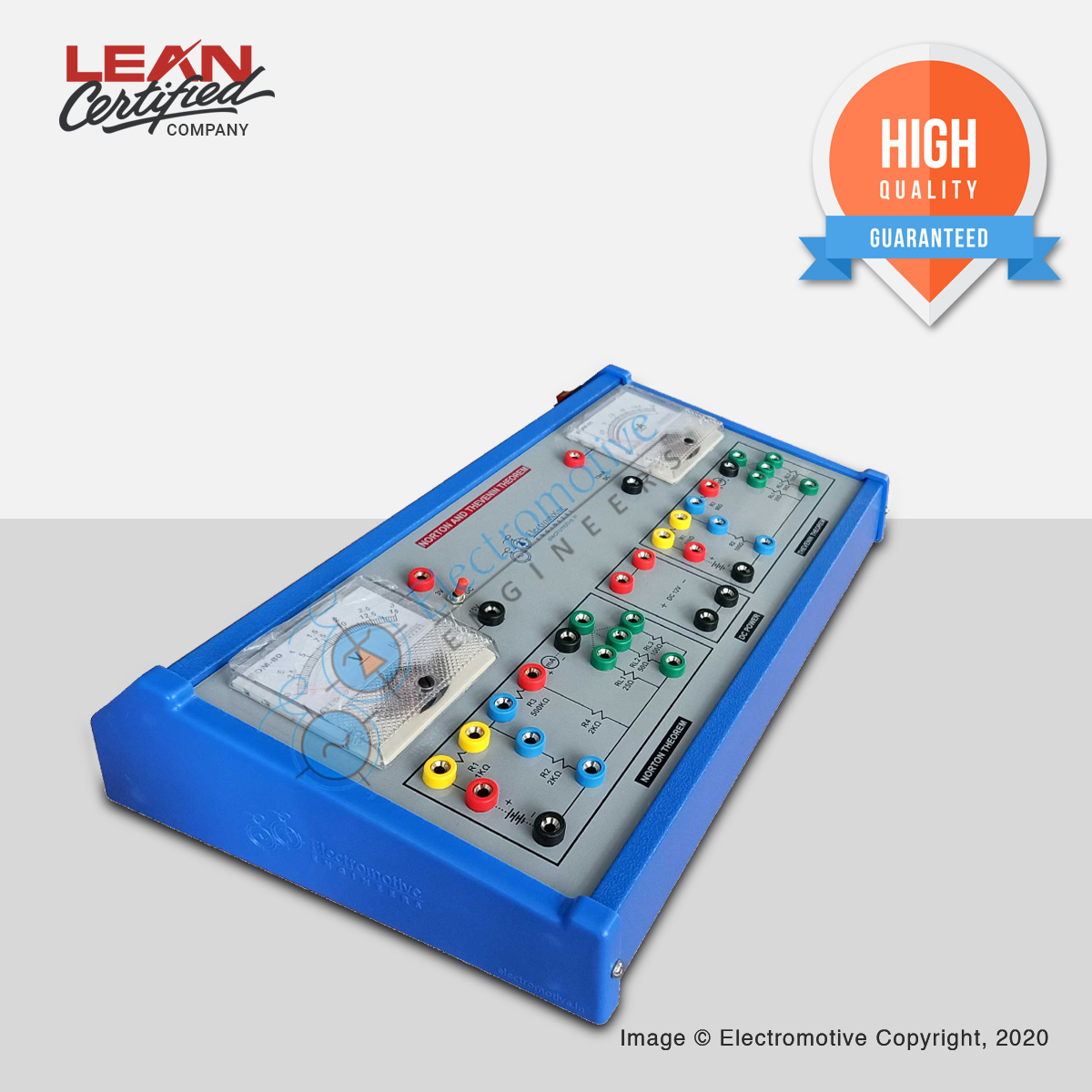
Norton and Thevenin Theorem
This trainer boards has one dual range EDM80 square meter and one milli-ammeter. Also fitted with regulated power supply of 12V @ 250mA....
₹5,400 -
₹4,380
![]()
![]()
Study of Half and Full Adder Circuit
Training board is fitted in built power supply of 5V DC, three logic input switches, three output logic indicators, one half adder and...
₹4,380 -
₹4,700
![]()
![]()
Study of Impedance in RLC Circuit
Training board is fitted with two square meters, in-built ac power supply (selectable voltage of 40V, 60V or 80V AC) and one resistance...
₹4,700